Computer Graphics with OpenGL
This is my personal notes for Computer Graphics with OpenGL course. The materials are compiled from several resources.
Chapters Overview
1. Computer Graphics
Computer Graphics (CG) is a branch of Computer Science (CS) (and also the products: video games, multimedia apps) that explores the creation of 2D and 3D graphics. It involves the process of creation, manipulation, and rendering of the visual objects using computer to the screen.
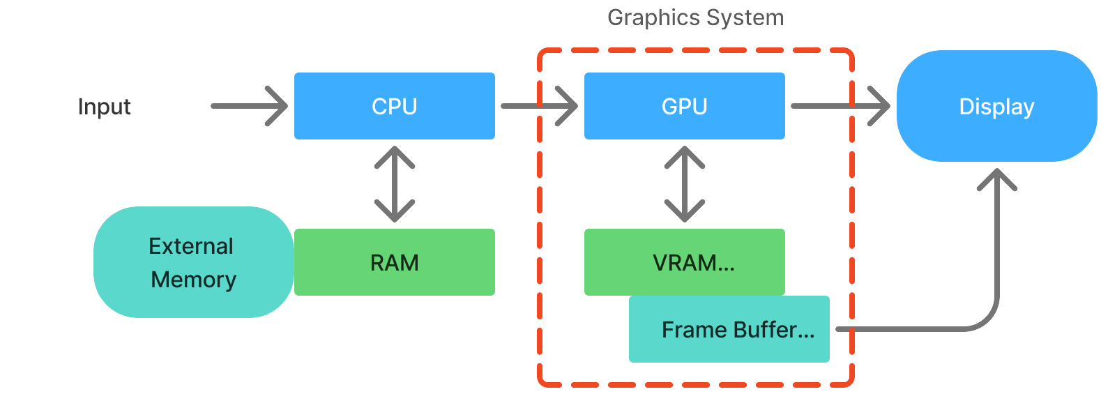
How? The system take graphical objectss (points, etc) and feed it to CPU where it will communicate the data flow from RAM to the graphics system. The graphics system which contains GPU and graphics memory (VRAM and buffers), will process the graphical operations. Finally, the Graphics subsystem (either GPU or buffers) may directly render the CG to the display.

Computer Graphic Overview inspired from [CS NTU Singapore](https://www3.ntu.edu.sg/home/ehchua/programming/opengl/CG_BasicsTheory.html).
OpenGL
OpenGL (Open Graphics Library) is a cross platform and open-source API for 2D and 3D graphics rendering, using c++. It commonly used in multimedia applications such as video games, CAD (computer-aided design), and scientific visualization apps. It utilizes GPU for hardware-accelerated rendering.
How? It provides functions that send instructions to GPU how to render shapes, apply textures, and manipulate many things. Basically, the process is like this:
- Our program send the graphics data (vertices, primitive shapes) into the vertex shader process. We can manipulate some of the process, but some are just fixed from OpenGL.
- The data is then applied with our intended manipulation (apply color, etc).
- Then the system will convert our imaginary data into array of pixels (image). We can still apply some manipulations on the curent data (fragment).
- Finally, display the pixels onto the screen.
I will explain in more detail and with correct terminology for each process in the next chapter. Anyway, here are some most common OpenGL libraries that is commonly used:
| Category | Library |
|---|---|
| C++ | Programming language. It can be compiled into the native machine. |
| GLFW or freeglut | Windowing management. Provides functionalities to handle the window and input. |
| GLEW or GLAD | Extension library. Provides abstraction of GPU functionalities for easiness. |
| GLM | Math library. Header-only lib that provides mathematical calculations. |
| SOIL2 | Texture management. Provides texture loading, etc. |
Before going further, understand this: OpenGL does not actually draw to computer screen. It renders to a frame buffer. Then, the individual machine must then draw the contents of the frame buffer onto a window on the screen. In reality, a buffer is a region of memory allocated by GPU to store data (graphics). It is important for transferring data between CPU and GPU, and are used in various OpenGL operations like rendering and shader processings. You can think of a buffer will be used to send the data as input and output of each shader stage.
2. OpenGL Graphics Pipeline
Basically, in computer graphic program, there are two parts of programming:
- Application (C++/OpenGL): an implementation of the graphics library calls using some specific programming language, usually C++, because it is the most popular and the best choice in terms of performance (because software side,- OpenGL’s API is written in C; the calls are directly compatible with C and C++). Although, language bindings (or wrappers) like Java and Python are also available. This part is runs on the CPU (compiled), and we refer this part as C++/OpenGL application. Another task of this part is to install (upload) the shader code (GLSL) into the GPU.
- Shader (GLSL): shader is run on GPU (hardware) to speed up graphics processings because it can handle matrices operation so fast (because graphics is full of math and metrices operations). Our C++/OpenGL program is responsible to obtain the shader code, either from files or hardcoded as strings, and it then create an empty shader object and loads them into it. Then, it also compile and link the shader object and install them on the GPU. Our C++/OpenGL program will still have access of the shader program in GPU. Another shader language is HLSL which works in Microsoft’s framework DirectX.
Both parts, C++/OpenGL application and the shader program will complimentary creating the our computer graphics program. The general cycle of an OpenGL application is as following:
- Initialize window.
- Initialize other libraries.
- Initialize OpenGL shaders.
- Call display() in a loop. It has function to clear the screen, and functions to process according to the pipeline.
So, what is a graphics pipeline? It is the processes of converting 3D scene (graphics) to a 2D image which are broken into a series of steps. OpenGL and DirectX utilize similar pipelines.
The OpenGL rendering pipeline is a sequence of steps that process and transform data (like vertices and textures) to generate the final image on screen. It has several stages, which can be programmable (like shaders) or fixed-function.
Double buffering is an important concept in OpenGL, it means that there are two color buffers - one that is displayed, and one that is
being rendered to. After an entire frame is rendered, the buffers are swapped. Double buffering is used to reduce undesirable visual artifacts. With this, human eyes will not realise the changing of the pixel.

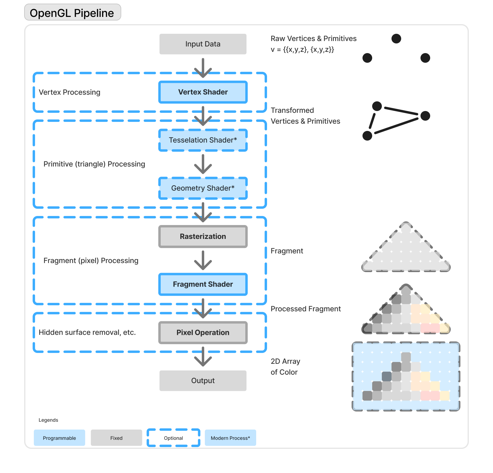
OpenGL Pipeline.
This illustration is inspired by https://www3.ntu.edu.sg/home/ehchua/programming/opengl/CG_BasicsTheory.html and https://learnopengl.com/Getting-started/Hello-Triangle.
Originally, the basic process of OpenGL Pipeline is this:
- Vertex Processing: define the geometry (ex: triangle vertices) and upload it to the GPU, and apply transformation to each vertex. Calculates vertex attributes like normals, colors, or texture coordinates. Think of it as placing and preparing the vertices of shapes in 3D space.
- Rasterization: converts primitives (ex: triangle) into fragment (pixel). Determines which screen pixels are covered by each primitive. Interpolates vertex data (like color/texture) across the shape. This turns geometry into the flat shapes you see on screen.
- Fragment Processing: calculate final pixel color for each fragment. Each fragment (potential pixel) is processed in the fragment shader. This is where you compute the final color, apply lighting, texturing, etc. It’s like painting each pixel with details - shadows, light, texture, etc.
- Pixel Processing : or sometimes also called “per-sample operation”, applying other operation like depth testing (hidden surface removal), blending, etc. Decide if a fragment becomes a pixel. Final result is written into the framebuffer (what’s shown on scree). It filters and blends fragments before they actually appear as pixels.
In reality, it is usually necessary to provide shader (GLSL) code for at least the vertex and fragment stages.
Then, the modern OpenGL is developed, adding Tesselation and Geometry shader. The pipeline imporved into this:
- Vertex Processing
a. Vertex Specification b. Vertex Shader (programmable - mandatory) - Primitive Processing
a. Tessellation Shader (programmable - optional)
b. Geometry Shader (programmable - optional) - Fragment Processing
a. Rasterization (fixed)
b. Fragment Shader (programmable - mandatory) - Per-Sample (Pixel) Operations (fixed)
(HSR, Blending, Depth Test, etc.)
I will explain all the stages in the pipeline in the next chapter.
3. Detailed Pipeline
1. Vertex Processing
To actually able to draw, OpenGL has to create at least a vertex shader and a fragment shader. Even when you do not explicitly code it, it is actually has the default (unseen) to do that.
1.1 Vertex Specification
It’s just how you define vertices that will be the shapes, and how do you define it? (hard coded “string” in the C++ program, hardcoded in the glsl, or even external shader (glsl) file ).
1.2 Vertex Shader
All the things OpenGL can draw is actually formed from simple things such as points, lines, and mostly triangles - those are called primitives, all those made up of vertices. As I mentioned earlier, the vertices data can be stored in text files or hardcoded as string in our C++ program or even in GLSL code itself. Our C++/OpenGL application must compile and link GLSL vertex and fragment shader programs, then load into the pipeline (using buffers).
Regardless of where they originate, all vertices pass through the vertex shader one by one; the shader is executed once per vertex.
In the actual code implementation, vertex and fragment shaders look like this:
 GLuint createShaderProgram() {
   const char *vshaderSource =
      "#version 430    \n"
      "void main(void) \n"
      "{ gl_Position = vec4(0.0, 0.0, 0.0, 1.0); }";
   const char *fshaderSource =
      "#version 430    \n"
      "out vec4 color; \n"
      "void main(void) \n"
      "{ color = vec4(0.0, 0.0, 1.0, 1.0); }";

   GLuint vShader = glCreateShader(GL_VERTEX_SHADER);
   GLuint fShader = glCreateShader(GL_FRAGMENT_SHADER);
   glShaderSource(vShader, 1, &vshaderSource, NULL);
   glShaderSource(fShader, 1, &fshaderSource, NULL);
   glCompileShader(vShader);
   glCompileShader(fShader);

   GLuint vfProgram = glCreateProgram();
   glAttachShader(vfProgram, vShader);
   glAttachShader(vfProgram, fShader);
   glLinkProgram(vfProgram);

   return vfProgram;
 }
For now, you just need to know that there are two variables that load the vertex and the fragment shader sources (vshaderSource and fshaderSource), and variables to hold the shaders as shader objects (vShader and fShader).
So, the primary purpose of any vertex shader is to send a vertex down the pipeline.
2. Primitives Processing
2.1 Tessellation Shader
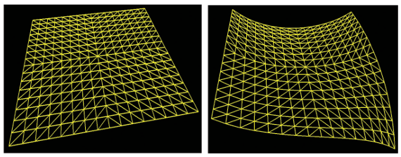
Tessellation stage is one of the most recent additions to OpenGL (in version 4.0). It provides a tessellator that can generate a large number of triangles, typically as a grid, and also some tools to manipulate those triangles in a variety of ways. For example, the programmer might manipulate a tessellated grid of triangles. So, it is much more efficient to have the tessellator in the GPU generate the triangle mesh in hardware, rather than doing it in C++.

Grid produced by tesselator taken from Computer Graphic Programming in OpenGL with C++.
2.2 Geometry Shader
The vertex shader gives the programmer the ability to manipulate one vertex at a time (i.e., “per-vertex” processing), and the fragment shader (as we will see) allows manipulating one pixel at a time (“per-fragment” processing), the geometry shader provides the capability to manipulate one primitive at a time-“per-primitive” processing.
By the time we have reached the geometry stage, the pipeline must have completed grouping the vertices into primitives (usually triangles) (a process called primitive assembly). The geometry shader then makes all three vertices in each triangle accessible to the programmer simultaneously.
There are a number of uses for per-primitive processing.
- The primitives could be altered, such as by stretching or shrinking them, or even deleting them to make a hole.
- Adding surface texture such as bumps or scales-even “hair” or “fur”-to an object.
It might seem redundant to provide a per-primitive shader stage when the tessellation stage(s) give the programmer access to all of the vertices in an entire model simultaneously. The difference is that tessellation only offers this capability in very limited circumstances - specifically when the model is a grid of triangles generated by the tessellator. It does not provide such simultaneous access to all the vertices of, say, an arbitrary model being sent in from C++ through a buffer.

Torus model and modified torus model.
3. Fragment Processing
Razterization is the process where the vertices and primitives are transformed into pixel locations (this is called fragments), which the fragments will be processed by the fragment shader. The fragment shader sets the RGB color of each pixel to be displayed. The default size of an OpenGL “point” is one pixel. When the rasterizer receives the vertex from the vertex shader, it will set pixel color (and maybe size?) values that form a point having the intended size.
As we mention, when sets of data prepared for sending down the pipeline, they are organized into buffers. Those buffers are in turn organized into Vertex Array Objects (VAOs). If we hardcoded the simple points in the vertex shader, we did not need any buffers. But, OpenGL still requires at least one VAO whenever shaders are being used, even if the application is not using any buffers.
3.1 Razterization
Our OpenGL 3D world of vertices, triangles, colors, and so on needs to be displayed on a 2D monitor. That 2D monitor screen is made up of a raster - a rectangular array of pixels. When a 3D object is rasterized, OpenGL converts the primitives in the object (usually triangles) into fragments. A fragment holds the information associated with a pixel.
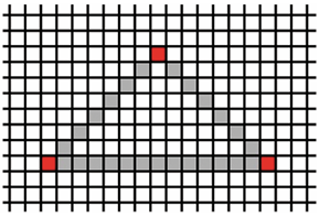
Rasterization determines the locations of pixels that need to be drawn in order to produce the triangle specified by its three vertices. The razterazation will interpolate pixels between three vertices (in a triangle). Any variable that is output by the vertex shader and input by the fragment shader will be interpolated based on the corresponding pixel position. We will use this capability to generate smooth color gradations, achieve realistic lighting, and many more effects.

Initial interpolation in Razterization.
3.2 Fragment Shader
As mentioned, the purpose of the fragment shader is to assign colors to the rasterized pixels. However, GLSL affords us virtually limitless creativity to calculate colors in other ways. One simple example would be to base the output color of a pixel on its location. Recall that in the vertex shader, the outgoing coordinates of a vertex are specified using the predefined variable gl_Position.
In the fragment shader, there is a similar variable available to the programmer for accessing the coordinates of an incoming fragment, called gl_FragCoord. We can modify the fragment shader so that it uses gl_FragCoord (in this case referencing its x component using the GLSL field selector notation) to set each pixel’s color based on its location, as shown here:
 #version 430
 out vec4 color;
 void main(void)
 {
   if (gl_FragCoord.x < 200) color = vec4(1.0, 0.0, 0.0, 1.0);
   else color = vec4(0.0, 0.0, 1.0, 1.0);
 }
4. Pixel Processing
As objects in our scene are drawn in the display() function using the glDrawArrays() command, we usually expect objects in front to block our view of objects behind them. To achieve this, we need hidden surface removal, or HSR. OpenGL can perform a variety of HSR operations, depending on the effect we want in our scene. And even though this phase is not programmable, it is extremely important that we understand how it works.
Hidden surface removal is accomplished by OpenGL through the cleverly coordinated use of two buffers:
- The color buffer (which we have discussed previously), and
- the depth buffer (sometimes called the
Z-buffer).
Both of these buffers are the same size as the raster - that is, there is an entry in each buffer for every pixel on the screen.
As various objects are drawn in a scene, pixel colors are generated by the fragment shader. The pixel colors are placed in the color buffer - it is the color buffer that is ultimately written to the screen. When multiple objects occupy some of the same pixels in the color buffer, a determination must be made as to which pixel color(s) are retained, based on which object is nearest the viewer.
Hidden surface removal is done as follows:
- Before a scene is rendered, the depth buffer is filled with values representing maximum depth.
- As a pixel color is output by the fragment shader, its distance from the viewer is calculated.
- If the computed distance is less than the distance stored in the depth buffer (for that pixel), then:
- (a) the pixel color replaces the color in the color buffer, and
- (b) the distance replaces the value in the depth buffer. Otherwise, the pixel is discarded.
This procedure is called the Z-buffer algorithm,
Other Terminologies
Each rendering of our scene is then called a frame, and the frequency of the calls to display() is the frame rate.
In below, the application’s display() method maintains a variable x used to offset the triangle’s X coordinate position. Its value changes each time display() is called (and thus is different for each frame), and it reverses direction each time it reaches 1.0 or -1.0.
The value in x is copied to a corresponding variable called offset in the vertex shader. The mechanism that performs this copy uses something called a uniform variable.
For now, just note that the C++/OpenGL application first calls glGetUniformLocation() to get a pointer to the offset variable, and then calls glProgramUniform1f() to copy the value of x into offset. The vertex shader then adds the offset to the X coordinate of the triangle being drawn.
C++/OpenGL application:
// same #includes and declarations as before, plus the following:
float x = 0.0f;
float inc = 0.01f;
// location of triangle on x axis
// offset for moving the triangle

void display(GLFWwindow* window, double currentTime) {
   glClear(GL_DEPTH_BUFFER_BIT);
   glClearColor(0.0, 0.0, 0.0, 1.0);
   glClear(GL_COLOR_BUFFER_BIT);

   // clear the background to black, each time
   glUseProgram(renderingProgram);
   x += inc;

   // move the triangle along x axis
   // switch to moving the triangle to the left
   if (x > 1.0f) inc = -0.01f;
   // switch to moving the triangle to the right
   if (x < -1.0f) inc = 0.01f;

   GLuint offsetLoc = glGetUniformLocation(renderingProgram, "offset");
   glProgramUniform1f(renderingProgram, offsetLoc, x);
   // get ptr to "offset"
   // send value in "x" to "offset"
   glDrawArrays(GL_TRIANGLES,0,3);
   }
   . . .  // remaining functions, same as before
Vertex shader:
#version 430
uniform float offset;
void main(void)
{
   if (gl_VertexID == 0) gl_Position = vec4( 0.25 + offset, -0.25, 0.0, 1.0);
   else if (gl_VertexID == 1) gl_Position = vec4(-0.25 + offset, -0.25, 0.0, 1.0);
   else gl_Position = vec4( 0.25 + offset, 0.25, 0.0, 1.0);
}
Summary of the Pipeline
- Vertex Shader: Processes each vertex individually. Applies transformations (model, view, projection) and passes data (like normals, texture coords) to the next stage. Uses VBO (Vertex Buffer Object) and VAO (Vertex Array Object) to upload vertex data and structure to the GPU.
- VBO (Vertex Buffer Object): Stores vertex data (positions, normals, UVs, etc.) in GPU memory.
- VAO (Vertex Array Object): Stores the configuration of vertex attribute pointers - how to read the data from VBOs.
- EBO (Element Buffer Object) (aka Index Buffer): Stores indices to reuse vertices, letting you draw with fewer vertices by referencing shared ones (e.g., for triangles). An EBO is a buffer that stores indices to reference vertices in a VBO. Instead of duplicating vertices for each triangle, you provide an index list that defines how to connect existing vertices. This reduces memory usage and improves rendering performance. Used with
glDrawElements()instead ofglDrawArrays(). - In short,
- VBO = what the data is,
- VAO = how to interpret it,
- EBO = how to efficiently reuse it.
- Visual Analogy: Imagine you’re building shapes with LEGO.
- VBO = The box of LEGO bricks (actual vertex data like position, color, etc.).
- VAO = The blueprint/manual telling you how to assemble bricks into a shape (attribute layout, bindings).
- EBO = A shortcut list that says, “Use brick #0, #1, and #2 to make triangle 1, then reuse #0 and #2 for triangle 2” - it avoids repeating the same bricks.
-
Tessellation Shader: Optional stage that splits patches into finer primitives (triangles). Useful for adding detail dynamically based on level-of-detail or curvature. Includes Tessellation Control Shader (TCS) and Tessellation Evaluation Shader (TES).
-
Geometry Shader: Takes whole primitives (e.g., triangles) and can emit new geometry - like duplicating, extruding, or generating additional vertices. Useful for effects like silhouette outlines or geometry-based normals.
-
Rasterization: Converts vector data (points, lines, triangles) into fragments (potential pixels). It maps geometry to the screen space and determines which pixels each primitive covers.
-
Fragment Shader: Runs per fragment (potential pixel). Responsible for computing the final color, depth, and other attributes. Can use lighting, textures, and custom effects. Output is written to the framebuffer.
- Other:
-
Clipping: Removes parts of primitives outside the view frustum before rasterization. Ensures only visible geometry is processed further.
-
Depth Test: Compares fragment depth values to those already in the depth buffer. If a fragment is closer to the camera, it passes and replaces the old one.
-
Blending: Combines fragment output with existing pixel data in the framebuffer using blending equations (e.g., for transparency).
-
Framebuffer: The final storage where pixel data is written for display. Can be default (screen) or custom (for post-processing).
-